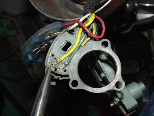
This Turn Signal Switch Assembly not only controls the L/R turn signal, but the brake lights wiring is routed through it! This is so a single wire can run to the rear stoplight/turn bulb, left or right, and allow simultaneous signaling and brake lights, all on one wire & one bulb filament per side. The two wires for Green right & Yellow left sides are split at the turn signal assembly.
For the 1967 Dodge model year the 5 wires going into steering column are Green [right turn signal outbound], Yellow [left turn signal outbound], Red [signal flasher, inbound from flasher], White [stoplight switch inbound from switch] & Black [horn circuit].
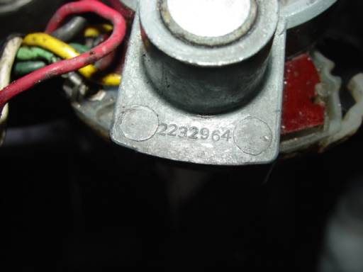
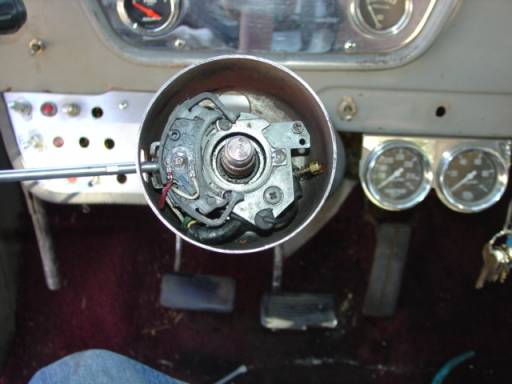
Turn signal assembly Mopar part number shown in picture below:
Last time I tried to purchase a turn signal switch assembly they were NLA, no longer available. The aftermarket seemed to have quit offering replacements for mine also, at least at that time, don't know about now? The design appears to prevent invasion, 'No user serviceable components inside'. Well, desperate situations call for desperate measures so I sized it up and decided to tear it apart! Wouldn't work so nothing to lose but my mind, and it’s long gone anyway.
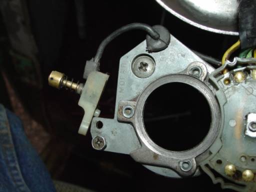
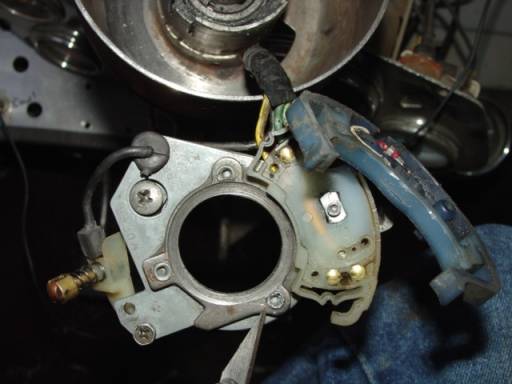
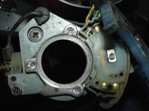
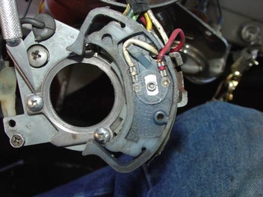
The wiring sub-assemblies are made of Nylon, a hard but flexible & very durable plastic, mounted on a zinc alloy pot metal base. The base is held to steering column by a largish Phillips screw, which pulls up a wedge clamp against column tube outer wall, clamp wedge shown at Exacto in picture below:

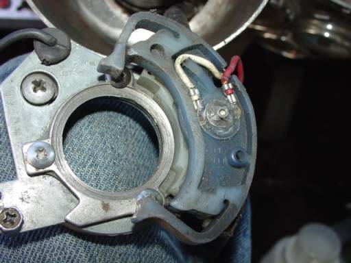
Turn signal assembly is modular, built in 3 sections. A mounting pin/spindle bolt on base passes up through 2 other switch sections allowing pivoting motion around central pin. Pot metal base assembly holds spindle bolt & contains a ball detent. The spindle bolt has the other 2 assy’s stacked on top of it, held in place by a small PAL nut [one of those flat stamped nuts]. Directly beneath the Pal nut there's a fiber insulation washer. Fiber washer only prevents PAL nut from shorting to wires.
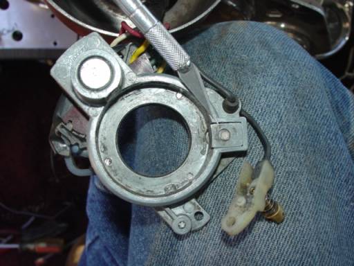
There’s also a roller tip contact pin for horn, held onto base by a screw & locator pin, shown removed in picture below:
The turn signal assembly has close tolerances so the only way I could find to remove PAL nut was to use a dental pick type probe and first break up the fiber washer. This gave enough clearance to get under & pry the PAL nut off. It may be physically possible to remove that PAL nut by prying up, without destroying fiber washer, but I wasn't able to. Pal nut shown below spindle bolt tip it was attached to, fiber washer already removed [see picture below].
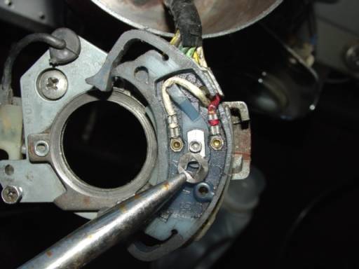
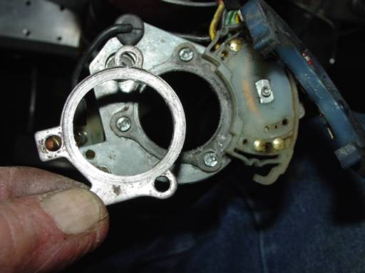
The 2 upper assemblies come apart from base, revealing a section with wiper spring-wires and another with contacts for those wiper wires [see picture below].
Once PAL nut is removed the T/S assemby breaks down into 2 parts: pot metal base with wiring sub-assembly attached by rivets to base & also wiper spring-wire sub-assembly. Wiper spring-wire assembly is the part that rotates left/right, as spindle bolt moves from signal lever movement, for controlling turn signal circuits. Turn signal lever threads into spindle bolt bottom and turns it for left/right signal, moving wiper wire sub-assembly across contacts in wired section. Wiper spring-wires at Exacto blade, brass contact buttons on left [see picture below].
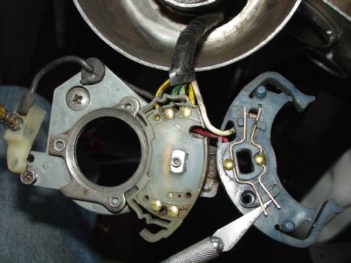
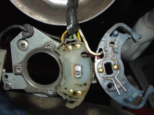
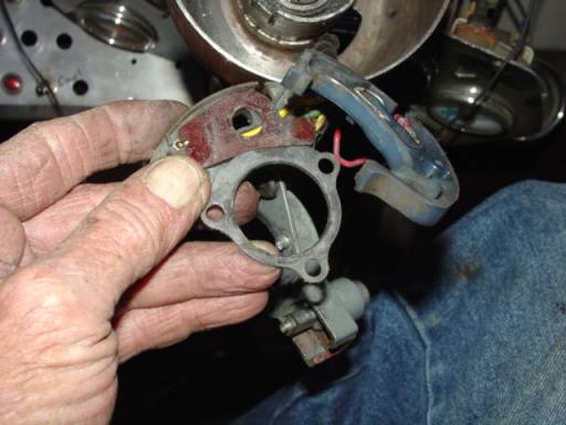
Looking at picture, upper contact buttons showing on left-hand assembly are wired as: Green on right button, yellow on left button. Lower brass contact buttons are opposite, Yellow on right button, Green on left button. Again, the chassis wiring has the Green wires running to Right side of vehicle, Yellow wires to Left side of vehicle. Yellow & Green wires are outbound, to lights.
Red wire is Signal Flasher inbound, White wire is Stoplight Switch inbound. With turn signal lever centered the wiper wires cause that power is routed through contacts to complete the circuit from stoplight switch wire to both combination brake/turn-signal lights.
Executing a Left turn signal pivots upper nylon assembly so that one wiper wire moves to keep the brake circuit active on Right side [of vehicle] wiring but also routes power from Signal Flasher through Left side [of vehicle] Yellow/Left wire, causing left side to flash & right side to be able to operate brake light from stoplight switch wire if activated by brake pedal. Right turn is the same, only different. :~ )
On my wiring sub-assembly I found signs of past overheating of brass contact buttons for wiper Red Signal Flasher wire. This melted the nylon, so it had to be carved gently with Exacto knife. I cleaned & polished the brass contact buttons too.
The wiper spring wires looked okay but it was deceiving. My initial problem was that everything worked except left rear brake lights. Looking closely at wiper spring-wires you’ll see they are captured in the nylon assembly. I found that the one end of wiper spring wire for left brake circuit contact was riding slightly lower in nylon assy., possibly caused by that prior overheating? This caused it to ride too high to hit the left side brake circuit brass contact button. It also seemed to be misaligned right/left over button. I simply bent the spring wire so it would wipe brass contact button for left rear as designed.
Side note: prior to noticing failure of left brake light I had some back-feed through left turn signal indicator light at dash, causing it to glow whenever I turned headlights on.
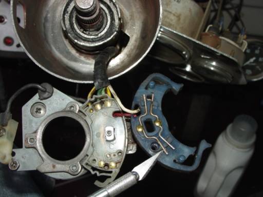
I thought I was good to go after repositioning that wiper spring-wire. Naw, too easy. I still didn’t have continuity in left side brake circuit. Of course this meant some deeper surgery, drilling out rivets in pot metal base assembly to remove wire connections sub-assembly. Spring-wire wiper sub-assembly in blue nylon & wiring sub-assembly in white nylon, and one of the 3 rivet heads in retaining ring at Exacto blade in picture below.
Using a very sharp drill bit sized to o.d. of ‘rivets’ I only drilled enough to just cut off rivet heads. Not actually rivets here, but little cast nibs that stand proud of cast base assembly, which same pass through nylon wiring sub-assembly body and then through a steel retainer ring, to be staked over at ends to hold the whole thing together. Partially drilled rivet head at tip of Exacto blade in picture below.
Retainer ring is steel, pot metal base forming rivets is very soft zinc alloy, softer than aluminum! Rivet heads fully drilled in picture below.
With the rivet heads cut off the retainer ring could be pried off and then all popped apart easily, see picture below. Retainer ring holds down white nylon wiring sub-assembly:
There is a reddish brown micarta insulator piece between pot metal base and white nylon wiring sub-assembly, see picture below. The piece held in grubby fingers looks like metal there but it’s white nylon. Pot metal base is hanging just below bottom hole in retainer ring, with a side view of spindle bolt. Ball detent is encased in fatter part of casting on right, spindle sticking out left & slightly downward, pic below:
I now found each wire to be staked in place on small brass pins. I was able to get the tip of needle nose pliers jaws over edge to crimp down the wire connections tightly. Crimping Green right-turn wire in picture below:
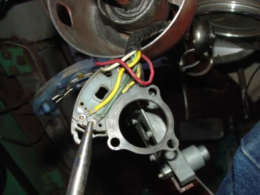
Crimping Yellow left signal wire in picture below:
Now all the problem areas are repaired, everything has been cleaned & lubed, ready for re-assembly. Whole unit was cleaned with cheapo [but perfectly good] Radio Shack ‘Electrical Contact Cleaner’ and lubed up with CRC. CRC does okay cleaning but contact cleaner & an old toothbrush is better, with CRC as a lube afterwards.
I re-assembled all parts and pressed the steel retainer ring down tightly onto the cast ‘rivets’ or nibs that stick up from base. I then used a sharp 1/8” bit to carefully & slowly drill down into exact center of base’s cast ‘rivets’. Make sure that retainer ring stays pressed down over nylon beneath while drilling holes as the ‘rivets’ may become deformed from drilling. Drill all the way through.
I then selected some small sheet metal screws, I think about a #4 or so, that measured 0.136” at outside of threads along shank. Their original length was 0.470 but I held them by the head in Vice Grips and put to the grinding wheel to cut them down to .275” - .250” threaded length, not counting head. When installed the screws would pass through base into area that steering column fits in and jam the works if they’re not ground off & wire brushed before insertion. Bench mount wire brush smoothes the ragged end of ground tip. Later pic shows screw protrusion.
Below is a picture of the steel retaining ring & nylon wiring sub-assembly re-installed on base assembly, with the new screws at Exacto taking the place of former ‘rivets’.
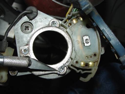
In next picture you can see how the new screws holding down retaining ring would protrude into steering column fitment area if they weren’t ground off, see picture:

That’s the screw tips showing along edge inside of recess in turn signal base. In that picture the spindle bolt bottom is the fat shiny steel pin in housing at upper left. Housing of base plate contains a ball-spring detent to maintain left-right-center positions. Black wire at upper right is horn circuit, at lower right is the horn roller contact’s plastic sub-assembly. Pin on plastic sub-assembly fits in upper hole and that boss below has the mounting screw for roller assembly. Roller tip passes through steering wheel & rides on a metal ring in horn button assembly, contact is made as horn button shorts connection to metal ring. Upper right, below black horn wire, you can see the moveable wedge that clamps the whole affair to the steering column.
Next up we need to re-install the uppermost sub-assembly, the part with wiper spring-wires attached to blue nylon housing that pivots with spindle movement, though it’s already shown in place in the next to last picture above.
Note in that next to last picture above, on right hand side the 2 wires, Red Signal Flasher & White Stoplight Switch, with a clear plastic washer over the protruding spindle tip? That plastic washer cost me $14 but it came with a Forney 4” cup brush. It’s a piece of the clear plastic packaging cut with scissors, with center hole punched with a General Hardware #72 English hole punch to about 0.155” diameter. If you’re even more bent towards the anal you could punch the outer circumference with one of those hollow core gasket hole punches, so that it’s perfectly round, scissors worked for me.
The PAL nut is next. Of course you want to be absolutely sure to put pressure on the bottom of that spindle bolt thingy while pressing down on uppermost blue nylon sub-assembly, so that tip of spindle protrudes and stays that way while PAL nut is forced down onto it.
Double check that your non-anal scissors-cut clear-plastic insulator-washer is firmly in place and set PAL nut on top of spindle tip. I was able to support spindle bolt bottom on rim of steering column bell, and use my 5/16” hollow-shaft nut driver to start it down square & parallel. Next my ¼” nut driver cinched it down pretty good, but not fully down. I had to use a fine-tipped jeweler’s screwdriver and some gentle love taps on the wings of biting surfaces of PAL nut to force them to grip the spindle tip. Installed picture below:
Now the entire assembly is ready for re-installation onto steering column, held by moveable wedge to column outer rim. Moveable wedge at Exacto blade in next picture:
On my truck I fabricated a steering column & shaft from assorted parts of ’78 Dodge D-200 column, welded to some of the original ’67 D-100 column for proper overall length. Then ’67 shaft was welded up with part of ’78 shaft for that length, connecting below at splined end into Borgeson universal joint. Unfortunately the column tube doesn’t want to play nice in the floor clamp at outer firewall, so it moves a bit regardless. That has caused all the wear marks seen in various pics on the nylon T/S Assembly etc.
Even on a bone stock installation you want the T/S Assembly fully down on column tube to prevent the wear I have, as mine also had drag & wear before modification. For those with this problem it’s also possible to grind down the bottom side of steering wheel to clearance it some.
While you’re in there at steering column bell you can check the steering shaft upper bearing wear & clearance, it retained in place by an external snap ring. At the least inject a healthy dose of chassis grease into the roller bearing with a pin-tip grease injector. There’s no chance of the grease fouling the upper T/S Assemblies because there’s no inertia to speak of during shaft movement.
Also inspect wiring for wear at sharp edges of steering column openings. Next picture shows the whole T/S Assembly is restored to steering column with wedge screw tightened, ready to rock!
Doubtless you’ve noted that it was never necessary to remove the Turn Signal Assembly & wiring from the truck! In this surgical intervention there was complete success, all functions restored and smooth precise operation resulted.
Next I need to change out the funky temporary dash toggle switches, finish the add-on dash at lower left, install the switch indicator lights & toggle switches in that auxiliary panel and get out the old rattle can paint. And then, and then……! Always something in this ongoing labor of love, huh? Enjoy yourself…. :~ )
JimmieD
Copyright 2009 - DTA Dodge Truck Association
Please include this link to DTA for any use off site: DTA Dodge Truck Association, Turn Signal Repair